Virtual Bright-Field Images Stack
The STEM discussion in Conventional TEM / Bright-Field STEM Reciprocity describe a conventional BF detector, which records a single intensity value per STEM probe position. However, with high-speed direct electron detectors, we can record a full image of the diffracted electron beam at each probe position Tate et al., 2016. By recording 2D images of of the STEM probe over a 2D grid of probe positions, we produce a four dimensonal dataset. This family of STEM methods is often referred to as four dimensional STEM (4D-STEM) Ophus, 2019. We can produce BF STEM images from a 4D-STEM dataset by using virtual detectors composed of integration masks applied in the diffraction space dimensions of a 4D-STEM dataset Ribet et al., 2023. The algorithmic and software implementation for various phase contrast 4D-STEM imaging methods are described in the manuscript by Varnavides et al. (2023).
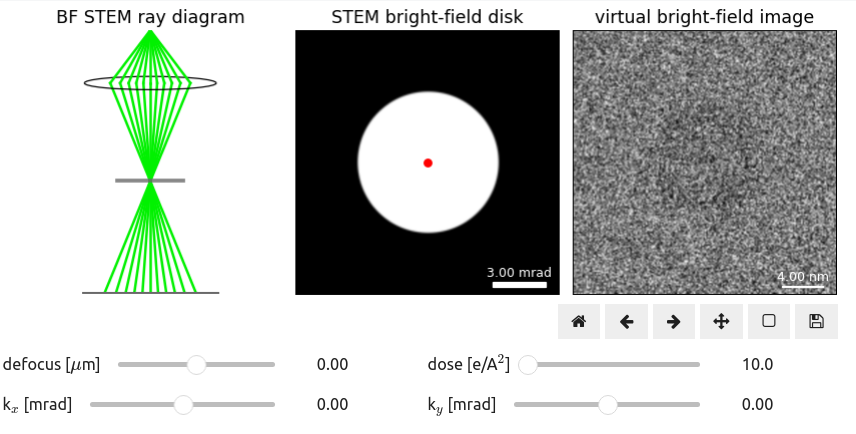
Using the principles of reciprocity described in Conventional TEM / Bright-Field STEM Reciprocity, we can examine in more detail how aberrations impact virtual imaging in STEM. First, we can consider the image resulting from the center most pixel of a bright field disk. This image is formed by integrating in reciprocal space the area highlighted by the red dot in Figure 1 to produce a 2D-real space image from a 4D-STEM data. This image is analogous to a conventional TEM image at the same conditions. More generally in STEM imaging, as the collection angle is decreased, diffraction contrast increases, and the resulting image looks more like a TEM bright field image Carter & Williams, 2016. Using the defocus slider in Figure 1, you can see in the image on the right the contrast changes and Fresnel ringing that arises in conventional TEM imaging as a function of aberrations.
As we saw, the STEM probe covers many pixels in diffraction space, each of which is analogous to an incoming plane wave for TEM imaging but at a different tilt. When defocused, the tilted illumination produces image shifts, which can be seen by changing the and sliders in Figure 1. The magnitude of the shifts changes with increasing defocus, which is based on the geometry of a defocused probe, as illustrated on the left. The impact of various aberrations on the shifts is explored in more detail in Aberration Fitting.
- Tate, M. W., Purohit, P., Chamberlain, D., Nguyen, K. X., Hovden, R., Chang, C. S., Deb, P., Turgut, E., Heron, J. T., Schlom, D. G., Ralph, D. C., Fuchs, G. D., Shanks, K. S., Philipp, H. T., Muller, D. A., & Gruner, S. M. (2016). High dynamic range pixel array detector for scanning transmission electron microscopy. Microscopy and Microanalysis, 22(1), 237–249. https://doi.org/10.1017/S1431927615015664
- Ophus, C. (2019). Four-dimensional scanning transmission electron microscopy (4D-STEM): From scanning nanodiffraction to ptychography and beyond. Microscopy and Microanalysis, 25(3), 563–582. https://doi.org/10.1017/S1431927619000497
- Ribet, S. M., Ophus, C., Dos Reis, R., & Dravid, V. P. (2023). Defect contrast with 4D-STEM: Understanding crystalline order with virtual detectors and beam modification. Microscopy and Microanalysis, 29(3), 1087–1095. https://doi.org/10.1093/micmic/ozad045
- Carter, C. B., & Williams, D. B. (2016). Transmission electron microscopy: Diffraction, imaging, and spectrometry. Springer. https://doi.org/10.1007/978-3-319-26651-0


