Conventional TEM / Bright-Field STEM Reciprocity
Conventional TEM
Conventional transmission electron microscopy (CTEM) refers to a TEM imaging mode where we form a plane-wave of electrons focused on (or close to) an electron-transparent sample De Graef, 2003. In bright field (BF) CTEM imaging we use a post-specimen aperture which only allows unscattered electrons to hit the detector. Alternatively we can produce a dark field (DF) image by using an aperture to select a subset of the scattered electrons. As discussed in Phase Contrast Imaging, we can use a phase plate or defocus to produce contrast without an aperture. CTEM is widely used for imaging biological specimens Cheng, 2015, weakly-scattering materials science or geological samples Lee, 2010, and for in situ experiments where we typically want high temporal resolution while observing a large field of view Ross, 2007.
Scanning TEM
An alternative imaging mode to CTEM is scanning transmission electron microscopy (STEM) Pennycook & Nellist, 2011. In STEM, we use a large aperture in the condenser plane, which forms an electron probe composed of a cone of illumination angles. The objective lens focuses this probe onto the sample, and electromagnetic or electrostatic scan coils are used to raster the probe over the sample surface Grigson, 1965. STEM has many flexible imaging and diffraction modes as well as the ability to collect spectroscopic signals such such as x-ray energy dispersive spectrometry (XEDS) Watanabe, 2016 and electron energy loss spectroscopy (EELS) Egerton, 2008, and is therefore widely used in materials science studies Ophus, 2023. In BF STEM, we measure the diffracted electron beam in the far field, using a detector centered on the optical axis which covers either a subset of the illumination angles or the full illumination cone LeBeau et al., 2009.
Principle of Reciprocity
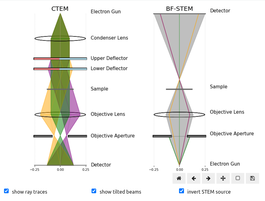
CTEM and BF STEM can be related using the concept of reciprocity. The principle of reciprocity in electron microscopy states that rays connecting a source to a detector follow the same optical path as the rays from the detector to the source Krause & Rosenauer, 2017. Figure 1 shows how this principle applies to CTEM and BF STEM, if we swap the source and detector positions for the STEM diagram.
By following the deflected rays from source-to-detector in CTEM and detector-to-source in STEM we can see reciprocity in action. Notice also how the deflected rays impact the sample at different positions, giving rise to the apparent image shifts the tcBF-STEM technique uses to reconstruct the phase, and how the magnitude of these shifts depend of the defocus as we will investigate in Virtual Bright-Field Images Stack.
- De Graef, M. (2003). Introduction to conventional transmission electron microscopy. Cambridge university press. https://doi.org/10.1017/CBO9780511615092
- Cheng, Y. (2015). Single-particle cryo-EM at crystallographic resolution. Cell, 161(3), 450–457. https://doi.org/10.1016/j.cell.2015.03.049
- Lee, M. (2010). Transmission electron microscopy (TEM) of Earth and planetary materials: A review. Mineralogical Magazine, 74(1), 1–27. https://doi.org/10.1180/minmag.2010.074.1.1
- Ross, F. M. (2007). In situ transmission electron microscopy. In Science of Microscopy (pp. 445–534). Springer. https://doi.org/10.1007/978-3-030-00069-1_3
- Pennycook, S. J., & Nellist, P. D. (2011). Scanning transmission electron microscopy: imaging and analysis. Springer Science & Business Media. https://doi.org/10.1007/978-1-4419-7200-2
- Grigson, C. (1965). Improved Scanning Electron Diffraction System. Review of Scientific Instruments, 36(11), 1587–1593. https://doi.org/10.1063/1.1719398
- Watanabe, M. (2016). Practical aspects and advanced applications of XEDS. Transmission Electron Microscopy: Diffraction, Imaging, and Spectrometry, 467–503. https://doi.org/10.1007/978-3-319-26651-0_17
- Egerton, R. F. (2008). Electron energy-loss spectroscopy in the TEM. Reports on Progress in Physics, 72(1), 016502. https://doi.org/10.1088/0034-4885/72/1/016502
- Ophus, C. (2023). Quantitative scanning transmission electron microscopy for materials science: Imaging, diffraction, spectroscopy, and tomography. Annual Review of Materials Research, 53(1), 105–141. https://doi.org/10.1146/annurev-matsci-080921-092646
- LeBeau, J. M., D’Alfonso, A. J., Findlay, S. D., Stemmer, S., & Allen, L. J. (2009). Quantitative comparisons of contrast in experimental and simulated bright-field scanning transmission electron microscopy images. Physical Review B—Condensed Matter and Materials Physics, 80(17), 174106. https://doi.org/10.1103/PhysRevB.80.174106
- Krause, F. F., & Rosenauer, A. (2017). Reciprocity relations in transmission electron microscopy: A rigorous derivation. Micron, 92, 1–5. https://doi.org/10.1016/j.micron.2016.09.007


