A Practical Guide to Scanning and Transmission Electron Microscopy Simulations
Mathematical Concepts
Here we briefly outline the mathematical concepts required to run STEM simulations.
Scalars, Vectors, Tensors, and Arrays
You are probably very familiar with the real numbers, which are values which measure a continuous quantity. These numbers can be integers such as 64, fractions such as , decimals such as -0.827 (a subset of fractions), and irrational numbers such as . These values are scalars, meaning there is only one number associated with each value, making them one-dimensional (1D).
By contrast, a vector is a value which cannot be represented by a single number. Examples include three-dimensional (3D) position coordinates , magnetic moments, or a set of three Euler angles that describe an arbitrary rotation in 3D space. Vectors are always one-dimensional. In the same way a vector generalizes the concept of a scalar, a tensor generalizes both vectors and scalars by extending a value to any number of dimensions. You are also likely implicitly familiar with image arrays, which are 2D tensors for a greyscale image, and 3D for a color image.
Complex Numbers
To model scattering in electron microscopy, we work with a special number system referred to as complex numbers. A complex number is a length-2 vector, where the two values are called the real and imaginary values. The real part of each number is the kind of real number as described as above. The imaginary part is also a real number, but multiplied by the imaginary unit . This unit is a number which satisfies the equation
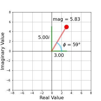
Examples of complex numbers include , , , and . Figure 1.1 shows examples of complex numbers. These are enormously powerful, and essential when performing calclations using quantum mechanics.
In addition to the real and imaginary parts, we can define two other useful quantities. The magnitude of a complex number is defined by its Euclidean length
This quantity is also sometimes referred to as the magnitude or the absolute value. The second quantity we define is the complex argument, defined as the angle ϕ from the real axis to the complex vector. Note that we usually want the signed angle, meaning we use which quadrant the complex value is located in to determine the signed angle using the expression
In programming, functions which measure this value are often named or . One of the most powerful identities using complex numbers is Euler’s formula
This expression links complex numbers to the trigonometric functions. This relationship foreshadows a key upcoming concept, namely that the trigonometric oscillations describe waves, where the physical concept of the complex angle will be mapped onto relative phase shifts of electron waves. We will therefore usually refer to the complex argument as the phase of a given complex value.
As we will see, even though computers internally store complex numbers using real and imaginary components as , it is often more intuitive for us to represent these numbers using their magnitude and phase, i.e. as .
We also sometimes take the conjugate of complex numbers, which means that we reverse the sign of the imaginary part. This operation is defined for a complex number as
or for as
1D Fourier Transform
The Fourier transform is an integral transformation that decomposes a function into its constituent spatial frequencies. This means that we write a function as a series of orthogonal sine waves with different frequencies / periodicities. A set of functions are orthogonal if we can multiply any pair of them and integrate over their domain to get a result of zero. The key property conveyed by this orthogonality is that the set of sine waves output by the Fourier Transform form a complete basis, and thus can represent any arbitrary function.
We can map a function over the coordinates to its Fourier transform over the ω coordinates using the expression
and we can recover the original function with the inverse transform
1D Discrete Fourier Transform
The Fourier transform is very useful for many mathematical analyses. However, we cannot use it in this form for this article, because unlike continuous variables such as position and frequency ω, our experimental images and simulated electron waves are sampled on discrete grids. We instead use the discrete Fourier transform, which transforms a finite-length function that has been sampled on a uniformly-spaced grid into its Fourier transform using the expression
where is the number of samples for both functions, and is the ’th sample of . The inverse DTF is defined as
where is the ’th sample of . Both and can be complex-valued. If either sequence is purely real-valued, the other will be conjugate symmetric, which means that if reverse the sequence and take the complex conjugate, we will recover the same sequence.
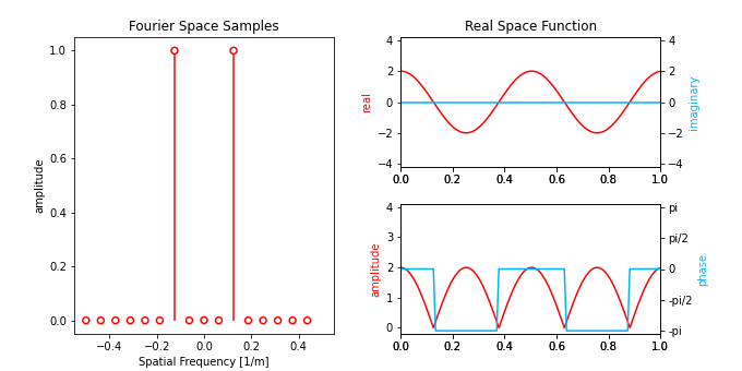
Figure 1.2 shows an interactive version of the 1D discrete Fourier transform. Try switching between the different preset functions. You can also change the amplitude of by clicking and moving the points up and down, or the phase by moving left and right. It can be difficult at first to gain intution for how changing the values of a given spatial frequency will change the output, but working in Fourier space will become second nature to you when you routinely perform STEM simulations.
2D Fourier Transforms
When simulating transmission electron microscopy images, diffraction patterns, and other wavefunctions, we are typically working with two-dimensional (2D) arrays. Thus we need to expand our previous definition to work in two dimensions. However, because this transformation is orthogonal over different Cartesian coordinates, we can compute a 2D discrete Fourier transform by simply sequentially multiplying the two transformations, giving
where is the pixel at indices for the function , which has total number of pixels in the and directions respectively. We can simplify this notation by combining the two sequential operations into one operator, giving the forward and inverse transforms
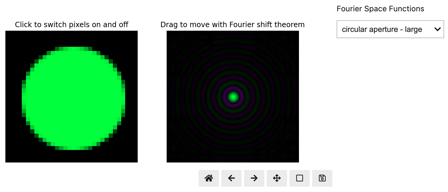
where and are the 2D coordinate systems for real and diffraction space respectively. As in the 1D case, in practice we use the fast Fourier transform (FFT) algorithm to compute these transforms with small computational overhead. Figure 1.3 shows an interactive version of the forward and and inverse 2D FFT.
On the left panel of Figure 1.3, you can click to swap individual pixels between 0 and 1 in Fourier space, while observing the response on the real space function. On the right panel, you can click and drag to shift the function by a distance , which is applied by using the Fourier shift theorem as
where is the expression corresponding to a plane wave. If you try dragging the real space function in Figure 1.3 a short distance, you will see the characteristic coloring of a plane wave, a periodically repeating rainbow function.
A deep understanding of the 2D Fourier transform is essential to both simulate and understand TEM experiments. Therefore in Table 1.1 we provide a table of Fourier transform pairs which are important for TEM. Note that for simplicity we have omitted some details such as some of the numerical prefactors in front of each function.
Fourier transform pairs
Table 1.1:2D Fourier transform pairs important in TEM simulation and analysis. Note that these transform pairs assume that both and are 2D, i.e. and .
| Diffraction space | Real space | ||
|---|---|---|---|
| Name | Function | Function | Name |
| Delta Dirac | 1 | plane wave along optic axis | |
| Shifted Dirac function | plane wave tilted to | ||
| diffraction spot pair | cosine wave | ||
| plane wave mult. | Shifted function | ||
| circular aperture | Airy disk function | ||
| defocus operator | Fresnel quadratic phase factor | ||
| Gaussian envelope | Gaussian envelope | ||
| exponential decay | 3D Lorentzian function | ||
| Lorentzian function | Modified Bessel func., kind |
Additional transform pairs can be found in the Wikipedia table of important Fourier transforms.


